
Sorry to bother you, just found the answer on the KiCAD forum and (in my opinion) it was way too obscure but this is what it is. Thank you for accepting me into this forum and I look fprward to getting straightened out about all this. SES structure? The existing documentation leaves me quite confused and like I said the guys iver there don't know anything about LE. Is that it or do I need to understand the. I'm trying to understand what my workflow ought to look like, I would think I let KiCAD Eeschema generate a netlist with footprints, I import that into KiCAD Pcbnew and do my placement so I get the advantage of their footprint libraries, then I output their. Now when I read about autorouting in KiCAD I hearall this about Specctra (.SES) importing and so forth which confuses me greatly. Now I understand KiCAD tried integrating autorouters before and now there's just a Java file of FreeRouting and it's not integrated in THAT tool but it is in LE which will also read KiCAD files. Like I said I'm on the KiCAD forums and I was asking about autorouting and everyone seems to want to tell me "oh you won't want to do THAT" and no one over there has even heard about LayoutEditor. I'm starting to migrate about 5 small PCBs into KiCAD, I already have the schematics almost all converted over and I'm bringing over the DXF board outlines.
#LAYOUTEDITOR JUSPERTOR BOARD WINDOWS 7#
Its comprehensive interface and shortcut associations make it a useful tool for technical designers.So I\m active on the KiCAD forums, I'm "a refugee" from a two-decade-old tool that I liked and it has an autorouter and it still works OK for me (it would autoroute a 4x4 inch board with 2 microcontrollers in 2 seconds which would then pass DRC) but it's getting to be a pain to support a tool that really only wants to run on a Windows XP-compatible system (I have Windows 7 Professional running in VirtualBox and it works fine but I would like a more versatile footprint library than this ancient tool). The application supports handling large designs, loading large files, importing elements or painting complex layouts can easily be performed.

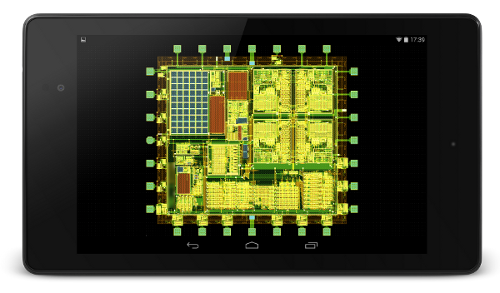
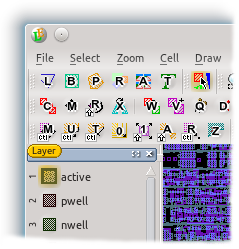
LayoutEditor is a powerful program that allows you to create several types of technical designs and schematics. The application uses a multitude of file formats, including Calma GDSII, OASIS, OpenAccess, CIF, DXF, Gerber, LEF, DEF, Lasi, SVG, CSV, PNG, Alliance, ODB++, EDIF or Qucs. Moreover, it allows you to manually modify the netlist, using the designated text editor. It also displays connections, device names, indicated routes, as well as extraction methods, for building connections or setting node modes. You may easily export netlists or import them from local files. The column on the left lists all the layers with their afferent names, as well as the current mouse shortcuts, while the panel on the right allows you to select netlist elements. LayoutEditor features a divided interface, with the main drawing area framed by useful function panels.

User-friendly interface for a quick design process Additionally, you can assign a multitude of functions to keyboard shortcuts. The application offers several types of tools for drawing and quickly switching between layers, as well as pre-defined shapes or the ability to make custom selections.

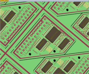
It is also suitable for the design of printed circuit boards (PCB), GDS thick film technology or thin film technology. It can come in handy when creating Multi-Chip-Modules (MCM), Chip-on-Board (COB), Low temperature co-fired ceramics (LTCC) or Monolithic Microwave Integrated Circuits (MMIC). LayoutEditor is a simple to use application which facilitates the design of circuits, chip boards or film technology. It is also suitable for designing circuits or film technologies. Moreover, the application offers a multitude of editing tools, designed to make the creation process faster and easier. LayoutEditor is a comprehensive program that allows you to quickly create, modify or export layout designs for MEMS/IC products.


 0 kommentar(er)
